Readers who found rodin ai by searching for STL to STEP conversion will learn how to prepare a mesh, turn it into a faceted solid, and check the result before CAD use.
An STL can become a solid that CAD software can measure, section, and cut—but conversion cannot restore the sketches and curves that made the original part. I start by checking the mesh and its units, then inspect the STEP result before using it in an assembly or a Boolean operation.
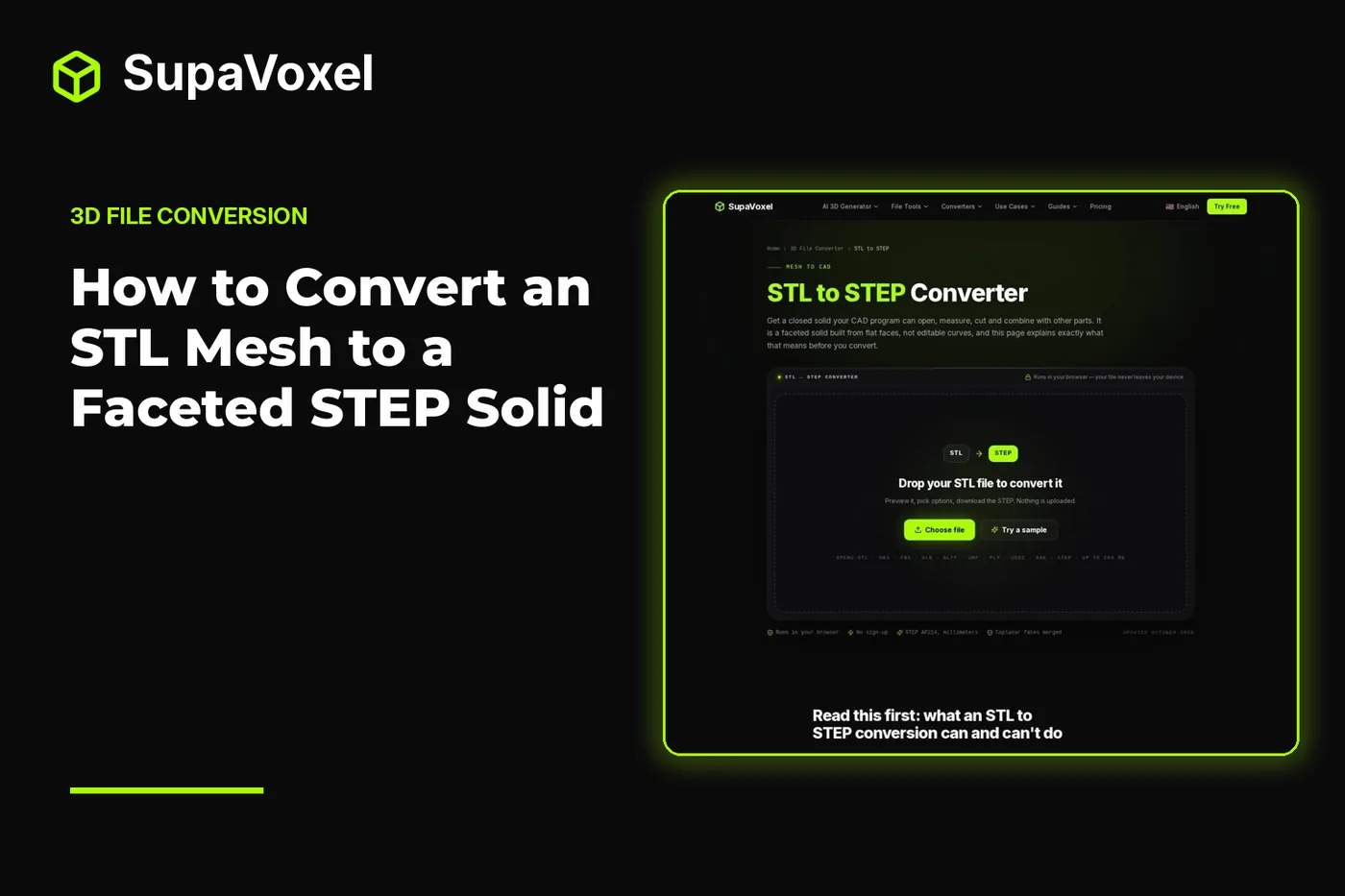
The short version
- Repair holes and open edges before converting. An open mesh cannot become the closed solid you need for reliable CAD operations.
- Check the STL’s apparent size. STL stores coordinates but does not declare their units.
- Use 3D Studio’s STL to STEP converter to write a millimeter-based STEP AP214 solid. It merges neighboring flat triangles where it can.
- Expect planar faces, not recovered sketches or editable cylinders. Inspect the exported body and its overall dimensions before building on it.
Step 1: Decide what the STEP solid needs to do
I convert an STL to STEP when the mesh needs to participate in a CAD task: checking its overall size, placing it beside another part, sectioning it, or subtracting its shape from a block. A faceted solid can do those jobs without pretending to be the original design.
The distinction matters because STL describes a surface with triangles. It does not say that a ring of facets represents a cylindrical hole, or that an edge once had a fillet. STEP can store exact CAD surfaces, but a converter cannot infer the missing design history from an STL. In this workflow, the STEP file contains a closed boundary made from the mesh’s flat faces.
Think about the operation you plan to perform after import. If you need the mesh as a reference for a cavity or an assembly check, the faceted body may be enough. If you need to change a hole diameter by editing a cylinder, conversion alone will not give you that control. Knowing the difference before you start saves a round trip through CAD.
Step 2: Inspect and repair the STL
Open the STL in a mesh viewer or editor and rotate it with wireframe visible. Look for missing patches, disconnected fragments, and edges that do not join another face. A non-manifold mesh has an edge or junction that does not define the boundary of a proper solid. For example, an open edge leaves a hole in the surface; a junction shared in an ambiguous way can make “inside” and “outside” unclear.
Repair those problems in a mesh-repair tool before conversion. The aim is not to make the model look smoother. It is to give the converter a closed surface from which it can build a solid. If the mesh contains separate shells, decide whether they are intentional separate bodies or stray pieces that should be removed.
Check density as well. A scan or detailed sculpt may have far more triangles than CAD needs for the intended operation. 3D Studio’s converter caps output at 200,000 STEP faces, and a dense curved mesh can remain expensive to open even when it fits under that cap. The page suggests reducing dense scans and AI meshes to 10,000 to 50,000 triangles before conversion. Preserve the details that affect fit, but do not carry unnecessary facets into a CAD assembly.
Step 3: Confirm units and convert
Drop a binary or ASCII STL into the converter. It accepts files up to 200 MB and shows the file size along with vertex and triangle counts. Use the preview and its wireframe view for a final check that you selected the intended mesh.

The converter shows the mesh before export, so you can check its density and output size.
Now read the output dimensions. This is the most important pause in the process: STL has no unit field. Its coordinates may have been written with millimeters in mind, or they may represent meters. The converter assumes millimeters unless you change File units. If the preview shows a part that is implausibly small, check the source units rather than scaling it by guesswork. For an STL saved in meters, select m.
Keep Z-up on for the expected CAD orientation, then select Convert to STEP. The downloaded file is STEP AP214 with millimeters declared inside it. The converter welds vertices and merges neighboring coplanar triangles. Flat regions therefore need not remain a patchwork of triangular CAD faces. Curved regions, however, remain collections of planar facets.
That face merging is useful, not magical. A flat side can become a convenient face for an added CAD feature. A round opening still consists of flat faces around its perimeter; selecting it will not reveal a diameter parameter.
Inspect the exported body
Before designing against the result, open the STEP file and check that it contains the bodies and overall size you expected. If CAD software is not at hand, 3D Studio’s STEP viewer opens .step and .stp files in the browser and shows the body count and bounding-box dimensions.

The STEP viewer provides a visual check of the exported bodies and their overall dimensions.
Orbit the model and look at areas where the original mesh had repairs. Check whether an intended opening is still open or an intended wall is complete. Compare the displayed width, depth, and height with the size you expected from the STL. This is also a useful way to catch a unit mistake before positioning the body in an assembly.
Do not mistake a bounding-box readout for detailed metrology. The viewer reports overall dimensions in millimeters, centimeters, or inches; it does not measure between selected points, inspect a hole diameter, or make sections. Use your CAD tool for those checks and for any cuts or combinations you intend to keep.
If the imported body feels cumbersome, revisit the source mesh rather than expecting STEP to compress curved detail away. Neighboring triangles on a plane can merge. Triangles following a curved surface still describe different planes, so they remain facets in the solid.
Work with the faceted solid in CAD
Treat the imported STEP as a body with a reliable outline, not as a recovered feature tree. You can position it in an assembly, measure or section it in CAD, subtract it from another solid to form a cavity, or add a feature from a suitable flat face. Separate meshes become separate solid bodies in the STEP file, which makes it worth checking the body count after import.
Pay particular attention to contact surfaces. A broad flat face is easier to use for a mating feature than a curved area broken into many small planes. If a Boolean cut produces an awkward boundary, inspect the corresponding STL surface: the cut follows those facets. More CAD commands cannot restore a curve that was absent from the mesh.
STEP is also not a way to carry all of an STL’s presentation data into CAD. The converter assigns one color per solid from its first material; it drops UVs, textures, and normals. For this task, judge success by the geometry, its size, and whether the resulting solid supports the operation you need.
Return to a print mesh only when needed
Do not convert an STL to STEP merely to send it back to a slicer. Slicers use mesh formats, so that detour adds no useful print geometry. Keep the original, repaired STL for printing when it is the file you want to slice.
There is a legitimate return path if you make meaningful changes in CAD. After adding or cutting solid geometry, 3D Studio’s STEP to STL converter can turn the revised .step or .stp file into a millimeter-sized STL for a slicer. Check its preview and output size before download. That conversion tessellates surfaces into triangles again; it does not turn the original faceted regions back into exact curves.
Keep the CAD file if later editing matters. Keep the STL for the printer. Each has a purpose, and neither format gains missing design history simply by being converted.
FAQ
Is the converted STEP file a real solid?
Yes. The converter writes a closed, faceted STEP AP214 solid that CAD software can measure, cut, and combine with other bodies. Its faces are planar; it has no recovered sketches or feature history.
Why is the STEP file larger than the STL?
STEP describes faces and their boundaries in much more detail than a compact binary STL describes triangles. Flat neighboring triangles can merge, but densely faceted curved surfaces still require many STEP faces.
Can I resize a hole after conversion?
Not by editing an original hole feature: the STL did not contain one. You can use the faceted body as a reference while creating new CAD geometry, but conversion itself does not reconstruct an editable cylinder.