Readers who came for rodin ai can use this guide to print two-color raised text with 3D Studio’s 3D Text Generator and a single-nozzle printer.
Two-color text does not require a multi-material printer when the color boundary is horizontal. Put the letters on a plate, use the plate thickness as the change height, and swap filament after the base finishes.
The short version
- Choose Plate in 3D Studio’s 3D Text Generator to put raised letters above a printable base.
- Note the plate thickness. Its default is 2 mm, and its top surface is the target for the filament change.
- Download an STL for a straightforward height-based change, or a 3MF if you want the plate and text as separate parts.
- In your slicer’s layer preview, place the change after the plate finishes and before the letters begin.
Why the plate thickness controls the color change
A single-nozzle printer lays down one filament at a time. It can still make a two-color sign if the design has a clear horizontal boundary: print the lower plate in one color, change filament, then print the raised letters in another.
The change height is the plate thickness, not the finished model height. If the plate is 2 mm thick, changing at 2 mm puts the new filament at the start of the lettering. A change below that point colors the top of the plate; a change above it leaves the bottoms of the letters in the plate color.
This approach is useful because every letter starts above the same base. You do not need a separate pause for each character. It will not, however, put different colors in neighboring letters that print on the same layer. That job needs a different material workflow or a design whose colors occupy different height bands.
The generator’s 2 mm plate default is a useful place to start. For a sign backed by a plate, 3–5 mm of raised lettering gives the text depth without requiring the default 8 mm. Check the preview’s overall dimensions as well as the thickness: a readable word is no help if it does not fit where you plan to print it.
Build the two-color text model
The text generator makes letters from font outlines and displays the model size while you adjust it. I set up the geometry before thinking about filament colors:
- Enter the wording. You can use up to 60 characters. Press Enter if you need another centered line.
- Pick a printable face. The font choices include bold options—Archivo Black, Titan One and Alfa Slab One—alongside Bebas Neue, the script faces Pacifico and Lobster, and the pixel-style Press Start 2P. I favor a bold face for small letters; thin details can disappear or close up.
- Size the letters. Letter height can be set from 5–80 mm. For a sign intended to read across a room, the page suggests 20–40 mm. Below 15 mm, its bold-font advice matters more, particularly with a 0.4 mm nozzle.
- Set the raised depth. The control spans 1–30 mm. For lettering attached to a plate, start with the page’s 3–5 mm sign guidance rather than making the letters unnecessarily tall.
- Select Plate and record its thickness. Plate creates the base under the text. Thickness ranges from 1–6 mm and starts at 2 mm; the value you choose is the height to locate in the slicer.
Before export, look at spacing and bevel. Script letters may need the suggested 5–10% extra spacing so their strokes do not run together. Bevel affects only the top edge; on a thin stroke, keep it below a third of that stroke’s width. The live size readout helps you catch a word that has grown too wide for its intended space.
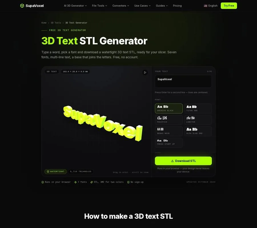
The generator preview lets you check the lettering, base choice and dimensions before export.
Choose STL or 3MF
For this manual filament swap, STL is sufficient. It describes the shape, so your slicer can see a plate with raised text, but STL does not carry colors, units or separate object structure. Confirm the imported size rather than assuming an STL has told the slicer what its units are.
With Plate selected, the generator also offers a two-color 3MF. Its text and plate are separate parts, which is useful if you want to inspect them independently or assign filaments on a multi-material printer. On a single-nozzle printer, that separation does not make the physical swap for you. You still need the change at the plate’s top.
If you want to examine the 3MF before opening a slicer, 3D Studio’s 3MF Viewer shows its objects in place, along with dimensions, mesh information and standard 3MF colors. That makes it a useful check that both the plate and lettering made it into the file.
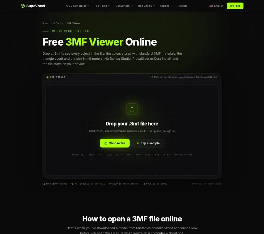
The viewer shows the file’s objects and size without requiring a slicer.
Do not treat a gray preview as proof that a 3MF has lost its colors. The viewer displays colors stored through standard 3MF materials, while some slicers store painting in their own project data. It also does not show print settings or supports. Use it to inspect the model; use your slicer to plan the print.
Add the filament change at the right height
The generator exports the text lying flat, so place it on its back in the slicer. It is intended to print in that orientation without supports. Then check the sliced layers rather than relying only on a typed height:
- Slice the model. The page recommends 0.2 mm layers for signs and 0.12 mm for smaller lettering.
- In layer preview, find the plate’s final layer. Compare its top height with the plate thickness you recorded.
- Insert a filament change or pause after that layer and before the first raised-letter layer.
- Start with the plate color loaded. At the change, load the text color and resume.
- Review the preview once more to make sure the boundary falls between base and letters.
With the default 2 mm plate and 0.2 mm layers, the boundary is easy to identify by height. If you choose a different plate thickness or layer height, let the sliced preview settle which layer completes the plate. Slicers may label the change by layer rather than millimeters; the visible transition matters more than the menu wording.
When separate text and plate parts are better
The 3MF is the stronger choice when a multi-material setup will assign one filament to the plate and another to the lettering. Its part structure also makes inspection easier: you can distinguish the base from the text instead of looking only at the combined silhouette.
For a manual change, pick whichever export your slicer handles most clearly. STL keeps the task focused on the height boundary. 3MF retains the distinct parts, but you must still check the sliced transition and add the change. Neither format replaces a look through the layer preview.
Base choice matters more than file type. Connected joins text with a rounded bar along the baseline; None leaves loose letters, including separate dots on letters such as i. Plate supplies the lower surface needed for this particular two-color sign. Keep it selected if you want a single change between base and lettering.
If the design is a logo instead of typed text
The text generator has bundled fonts rather than a font-upload option. For a particular typeface, turn the lettering into vector outlines first. 3D Studio’s SVG to STL converter then lets you extrude those outlines—or a logo—and export a multi-color 3MF with a part for each color.
That tool accepts designs with up to 8 colors and allows different extrusion heights for them. For a single-nozzle print, plan those heights carefully: a filament change can separate colors above and below a horizontal boundary, but it cannot independently color adjacent regions on the same layer. If a single color will do, the converter also offers a merged-color option.
At the final printed size, aim for features at least 1 mm wide. Convert live SVG text to paths, and use flat fills: live text is skipped by the converter, while gradients do not preserve their original appearance as color regions.
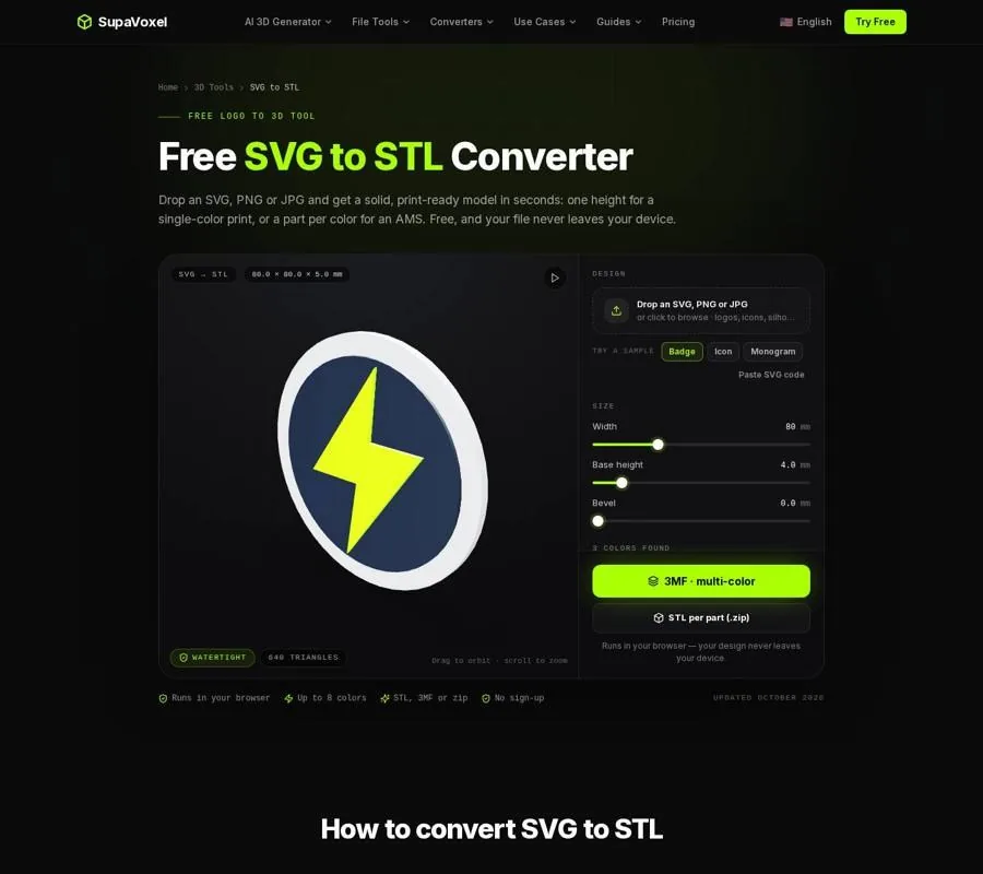
The SVG tool provides color-part and height controls for artwork that goes beyond the bundled text fonts.
For an ordinary name sign, Plate in the text generator is the simpler route. Use the SVG workflow when the exact lettering or artwork is the point of the print.
Final checks before printing
Before sending the job, I check the sliced result against the model I intended:
- Base — Plate is selected, rather than None or Connected.
- Boundary — The filament change follows the plate’s final layer and precedes the letters.
- Size — The imported model fits the intended print area, especially if I used STL.
- Detail — Small letters have enough stroke width, spacing and layer resolution to remain legible.
- Orientation — The sign lies flat on its exported back surface.
- Filament — The plate color is loaded, and the lettering color is ready for the pause.
If you need another browser-based check or a repair tool before slicing, 3D Studio’s 3D Tools directory groups viewers and print-preparation tools by task. For this print, though, the decisive check remains the slicer’s layer preview: it shows exactly where the new color will start.
FAQ
Can I use any plate thickness for the color change?
The generator offers 1–6 mm. Use the thickness you selected as your target, then confirm in the sliced preview which layer finishes the plate. The default target is 2 mm.
Should I download STL or 3MF for a single-nozzle printer?
Use STL if you only need the geometry for a height-based change. Choose 3MF if keeping the text and plate as distinct parts helps with inspection or a later multi-material print. Add and verify the manual change either way.
Why did the text change color too early?
Check where the pause sits relative to the plate’s final layer. A change before that layer finishes puts the second color on the plate. Move it to the transition between the completed base and the first letter layer.